


Below are the common hearing loop design configurations: phased array, perimeter, portable, and counter:
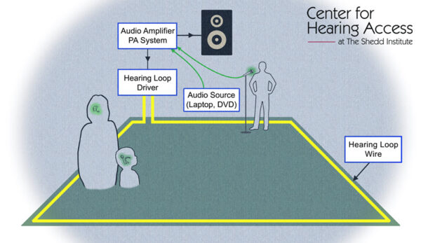
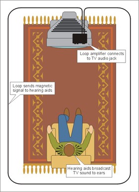
This diagram shows the basics of how a hearing loop works, with 4 components that are added to an existing PA system: audio source, hearing loop driver, hearing loop wire, and receivers in a person’s hearing aid or cochlear implant. The image also shows the blue mist where the electromagnetic field of sound is created, once audio is received. Note: a qualified installer can evaluate the best design: perimeter, multi-phase, etc.
Depending on the size of the room, use, and facility construction, different designs may be needed. Below are 2 basic designs. Please consult with a qualified installer who can evaluate the best design to meet IEC standards (webpage, this website)
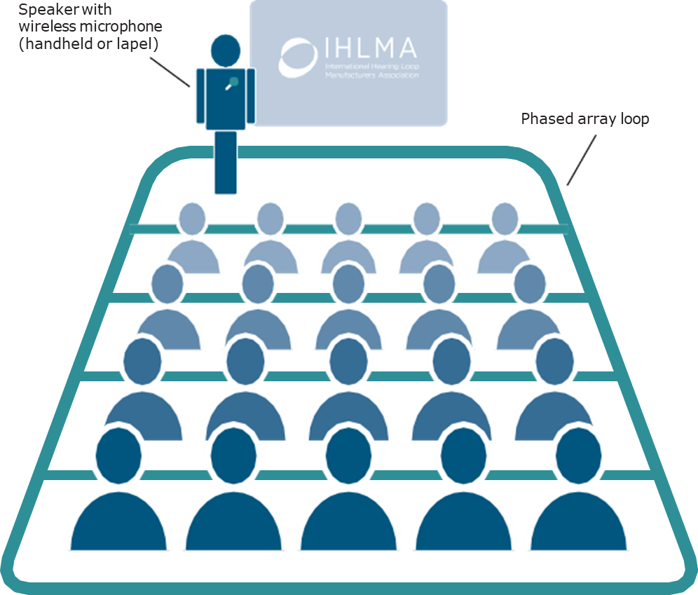
Phased array, used for large rooms. Well-designed phased array hearing loops give good, quality sound, no matter where a person sits.
Perimeter hearing loop, commonly used in small meeting rooms. Please consult with a qualified installer who can evaluate whether a perimeter hearing loop in the room will meet IEC standards. A person should be able to sit anywhere and be able to clearly hear through the hearing loop.
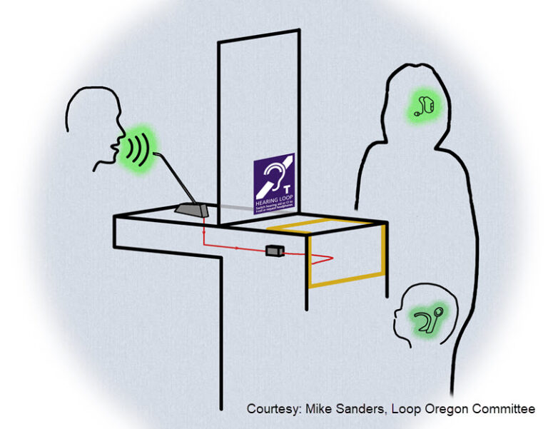
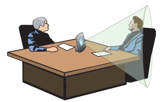
Blue mist. The area where the hearing loop will work is the “blue mist.” The size of the blue mist depends on the hearing loop design and settings; a customer’s hearing instruments; and a customer’s hearing loss. Generally, a customer hears best if their ears are approximately 2 feet in front of the counter hearing loop, but a weaker transmission may sometimes be picked up approximately 3-4 feet away. The further away the person is, the softer the sound will be and audibility quickly drops off. Also the hearing loop also radiates out to the sides, approximately 2 feet. This blue mist creates a field of privacy.
Fixed/Permanent Counter Hearing Loop. Generally, a “bent” hearing loop is best as it provides a signal in both planes: horizontal for a standing customer and vertical for a person using a wheelchair / seated user / child.
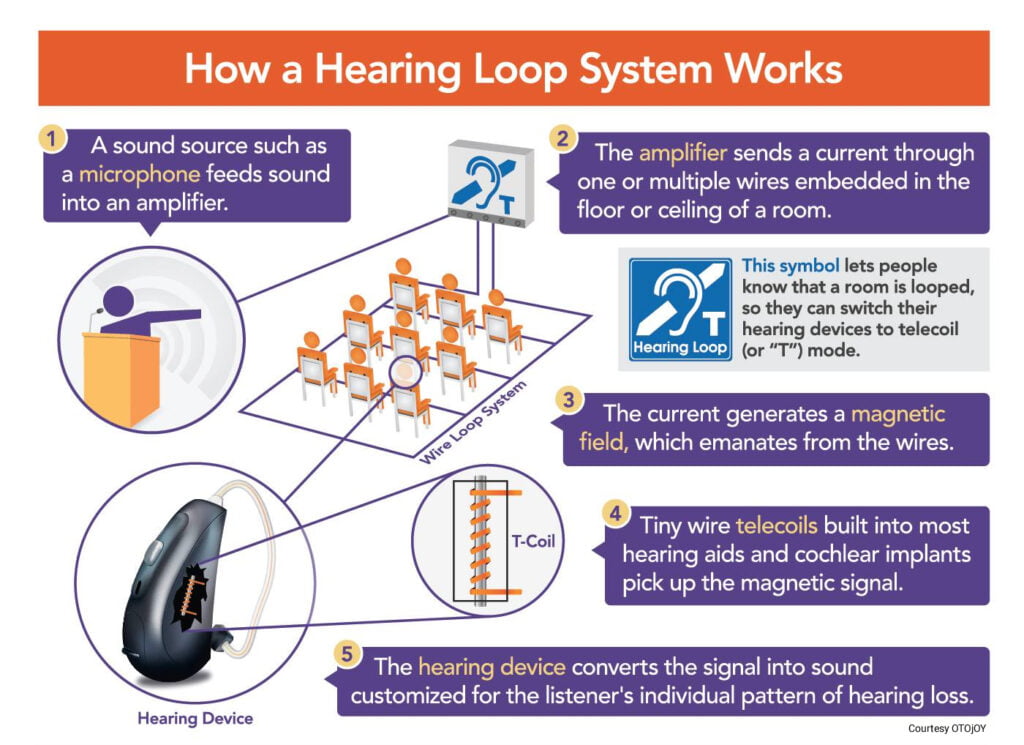
How hearing loop works with hearing aid and implant (1 page, pdf)
Watch how the components of a fixed/permanent counter hearing loop are gradually built:
Portable counter hearing loop. Generally, for best results:
A graphic showing how a counter hearing loop works along with the field strength
Graphic credit: University of Melbourne